Robotic Wheel Barrow
15.1 years ago arduino

If you ever have spent a day hauling soil/gravel you know this can cause some serious pains in your back. Now with the Lawnbot 400 you can save some pain and let the evil robots do the hard labor for you.
The project started as an arduino powered lawn mower with a custom PCB motor driver powered by a couple of wheel chair motors, which mike many projects he just couldn’t stop improving. Great work…
Tags: arduino, cheap, vegetables
How to make a grow box controller (Original)
15.1 years ago arduino, cheap, LEDs, vegetables

While my existing system was working I decided to make an upgrade to the electronics on my old system for several reasons:
- I needed to add more automated external controls (heater, fans, water pump) with my existing design this was entirely possible though was starting to get a little clunky.
- The existing controller (PS2 Controller, parallel port with various wires to control relays) worked but was not exactly compact.
- Wanted a modular design so if I needed to debug some issue I could simply unplug the USB and power and bring it out of the box in the garage for needed work
- Ability for others to create so I can share my software without forcing people to hack PS2 controllers to get to work
- Ability to use components like 1Wire temperature sensors (others to come) and Arduino
- Just for the fun of it
Well now I have attempted to justify my reasons this is what I used to put the whole thing together:
Parts List
- Black plastic project case (8”X6”X3”)
- Breadboard or multipurpose PC board
- soldering iron and solder (optional if using breadboard)
- Arduino
- 4 – solid state relays
- 4 — 1K resistor
- 4 — 2N2222 transistor
- 4 — 1N4004 diode
- DS18S20 (1Wire temperature sensor)
- 4.7K resistor
- (10K resistor and homemade soil sensor) or Vegetronix soil sensor
- 20 gauge solid copper wire (recommend multiple colors)
- Heavy duty extension cord
- 2 — outlet sockets
- 2 — socket faceplate (optional)
- hot glue gun and glue
If we had lawyers, they probably would want us to say this:
WARNING: I am not an electrician and do not pretend to be one. I do not know the specific building electrical codes of your area, so please be sure your wiring is completed under the proper safety code for your area. As always, using high voltage electricity can result in self-electrocution or burn down your house if not done safely so if you are not comfortable doing this wiring please contact a qualified professional.
Putting it all together
On the electronics side overall the circuits are actually pretty simple and if using a breadboard definitely something that could be tackled by a beginner. Though on the other side since this project is dealing with AC current I definitely would recommend caution (no hands unless power is unplugged) or have someone a little more comfortable with 120/220V help you out.
The Brains

I will be the first to admit that using an Arduino for this application is complete overkill for this application but it gives plenty of room for additions in the future. For all intensive purposes you could have your grow box completely controlled from the Arduino own processing power though on my case the software and UI is more interesting part to me. For this reason the Arduino code is actually very “dumb” basically just taking commands via the build in serial through USB and setting digital outputs to HIGH/LOW or reading analog inputs.
Here is the code for your grow box controller:
1: /*
2: * GrowBox Arduino Interface
3: *
4: * Descriptions: Simple interface to digital and analog controls by passing serial inputs
5: * For example:
6: * "A1" to read analog value on pin 1
7: * "D1H" to set digital pin 1 to HIGH
8: */
9: #include <OneWire.h>
10:
11: //1-wire
12: OneWire ds(8); // on pin 8
13: #define BADTEMP -1000
14:
15: //define unique sensor serial code
16: byte temperature[8];
17:
19: #define PIN_VALUE 1 // numeric pin value (0 through 9) for digital output or analog input
18: #define ACTION_TYPE 0 // 'D' for digtal write, 'A' for analog read
20: #define DIGITAL_SET_VALUE 2 // Value to write (only used for digital, ignored for analog)
21:
22: int NUM_OF_ANALOG_READS = 2;
23: char commandString[20];
24:
25: void setup()
26: {
27: Serial.begin(9600);
28:
29: setOneWireHex();
30:
31: // Power control
32: for(int i=0; i<=7; i++)
33: {
34: pinMode(i, OUTPUT); // sets the digital pins as output
35: digitalWrite(i, LOW); // turn everything off
36: }
37: }
38:
39: void loop()
40: {
41: readStringFromSerial();
42:
43: if (commandString[ACTION_TYPE] != 0) {
44: int pinValue = commandString[PIN_VALUE] - '0'; // Convert char to int
45:
46: if(commandString[ACTION_TYPE] == 'A')
47: Serial.println(analogRead(pinValue));
48: else if(commandString[ACTION_TYPE] == 'D') {
49: if(commandString[DIGITAL_SET_VALUE] == 'H')
50: digitalWrite(pinValue, HIGH);
51: else if(commandString[DIGITAL_SET_VALUE] == 'L')
52: digitalWrite(pinValue, LOW);
53:
54: Serial.println("OK");
55: }
56: else if(commandString[ACTION_TYPE] == 'T') {
57: float temp = get_temp(temperature);
58:
59: Serial.print(temp);
60: Serial.println("C");
61: }
62: else if(commandString[ACTION_TYPE] == '1') {
63: printOneWireHex();
64: }
65: else if(commandString[ACTION_TYPE] == 'V') {
66: Serial.println("VERSION_1_0_0_0");
67: }
68: else if(commandString[ACTION_TYPE] == 'P') {
69: Serial.println("PONG");
70: }
71:
72: // Clean Array
73: for (int i=0; i <= 20; i++)
74: commandString[i]=0;
75: }
76:
77: delay(100); // wait a little time
78: }
79:
80:
81: void readStringFromSerial() {
82: int i = 0;
83: if(Serial.available()) {
84: while (Serial.available()) {
85: commandString[i] = Serial.read();
86: i++;
87: }
88: }
89: }
90:
91: void setOneWireHex() {
92: ds.reset_search();
93: ds.search(temperature);
94: }
95:
96: void printOneWireHex() {
97: ds.reset_search();
98: if ( !ds.search(temperature)) {
99: Serial.print("NONE\n");
100: }
101: else {
102: ds.reset_search();
103:
104: int sensor = 0;
105: while(ds.search(temperature))
106: {
107: Serial.print("S");
108: Serial.print(sensor);
109: Serial.print("=");
110: for(int i = 0; i < 8; i++) {
111: Serial.print(temperature[i], HEX);
112: Serial.print(".");
113: }
114: Serial.println();
115: }
116: }
117:
118: ds.reset_search();
119: }
120:
121: float get_temp(byte* addr)
122: {
123: byte present = 0;
124: byte i;
125: byte data[12];
126:
127: ds.reset();
128: ds.select(addr);
129: ds.write(0x44,1); // start conversion, with parasite power on at the end
130:
131: delay(1000); // maybe 750ms is enough, maybe not
132: // we might do a ds.depower() here, but the reset will take care of it.
133:
134: present = ds.reset();
135: ds.select(addr);
136: ds.write(0xBE); // Read Scratchpad
137:
138: for ( i = 0; i < 9; i++) { // we need 9 bytes
139: data[i] = ds.read();
140: }
141:
142: int temp;
143: float ftemp;
144: temp = data[0]; // load all 8 bits of the LSB
145:
146: if (data[1] > 0x80){ // sign bit set, temp is negative
147: temp = !temp + 1; //two's complement adjustment
148: temp = temp * -1; //flip value negative.
149: }
150:
151: //get hi-rez data
152: int cpc;
153: int cr = data[6];
154: cpc = data[7];
155:
156: if (cpc == 0)
157: return BADTEMP;
158:
159: temp = temp >> 1; // Truncate by dropping bit zero for hi-rez forumua
160: ftemp = temp - (float)0.25 + (cpc - cr)/(float)cpc;
161: //end hi-rez data
162: // ftemp = ((ftemp * 9) / 5.0) + 32; //C -> F
163:
164: return ftemp;
165: }
Copy and paste the above code into your Arduino software. For the code above I used the OneHire.h library which is free to use and can be downloaded from here. To be able to use this library simply copy the contents to C:\arduino\hardware\libraries\OneWire. Now you should be able to Compile (CTRL+R) and upload the code to the board (CTRL+U)
Now with the software uploaded you can send some simple serial commands via its built in USB to serial adapter to interact with it. The interface is are broken up into 1 to 4 character commands, which I will detail below
| Command | Description |
| T | Returns temperature from One Wire component |
| D4H | Sets digital pin 4 to HIGH (ON) (replace 4 for alternate pin) |
| D4L | Sets digital pin 4 to LOW (OFF) (replace 4 for alternate pin) |
| A1 | Reads analog value from pin 1 (replace 1 for alternate pin) |
| PING | Returns PONG which is used to confirmed controller is online |
| V | Returns version which is some forethought into the PC application being able to support different versions of controller software |
Using the build in serial monitor tool in Arduino.exe, my application, or you should be able to control your Arduino with this very simple command based interface
Now you can hook up some LEDs and watch them blink which is fun for a little while but if you want to add some grow box components read on….
Temperature Sensor
As you can see I have fully embraced the circuit schema on the back of a napkin idea. These are the actual diagrams I crumpled up and stuffed in my pocket with several trips to the garage for some final soldering of various joints until everything was solid.
Below is the simple circuit required to get your 1Wire temperature sensor working. I would recommend checking your documentation (if not labels on the chip) for the orientation to have 1 and 3 correct, if you have it wrong you should get some complete unrealistic number. Hook ground up to pin1 on the DS18S20 and pin 2 hooked up to the digital input pin 8 on the Arduino with 5V with a 4.7K resister in between to step down the voltage.
If everything is hooked up correctly you should get the current room temperature in Celsius by sending command “T” to your Arduino. If you prefer Fahrenheit uncomment line 162 and recompile and upload your changes, though if using my software I support both degree types and do the conversion in the the software. To make sure everything working (or just to play with your new toy) put your fingers on the chip for a couple seconds and take another measurement unless you keep your house very warm the temperature should go up a couple of degrees

Turning things on and off (Relays)
If you were smart enough to check the current requirements of your Solid State Relays (SSR) before you bought them you may be able to skip this whole circuit and simply hook the digital outputs to the 5V positive side and ground to the negative side of the SSR.
Unfortunately if you are like me and bought some SSRs that require more current draw than the Arduino (or any other IC chip) of 40mA then you will need to create the simple circuit below.

Basic idea is pretty simple, you are using the output from the digital pins to switch of the transistor which then allows the ground to complete the circuit with the thus turning on the relay. As you can see there is a 1K resistor between the base (middle pin) of the transistor. If you are not using a SSR relay (though recommend you do) you should add a 1N4004 diode between the positive/negative which protects the transistor from being damaged in case of a high voltage spike which can occur for a fraction of a second when the transistor switched off, this is also known as a back-EMF diode or fly back diode.
Now here you have a couple options. If you are confident of our wiring skills you can do like I did and take a couple of sockets and hook up the neutral and ground in parallel. Two save space and since I really didn’t need two separate plug-ins (nor its own plug) for each relay I removed the little metal bar between the two sockets so they could be switched on independently. Now simply hook up hot to the left side of all your relays in parallel and then connect a wire from the right side of the relay to its own plug on the two sockets.
Now a less wiring intensive method is to simply take a 6 foot (small if you can find them) and cut the hot wire (usually the one with non-smooth wire) and attach each end of the wire to both sides of the relay.
Moisture Sensor
When it comes to a moisture sensor there are a few options. First is the classic two galvanized nails, second is the cheap gypsum soil moisture sensor which I have written up in the provided link. Lastly if my personal favorite the Vegetronix soil sensor.
If you use the Vegetronix hookup is simple no circuit needed simply hook up the 5V to red, bare wire to ground, and black to analog pin 1.
If you are using the other options you will need the simple circuit below. Technically it is a voltage divider, but that doesn’t really matter. Just hook up one end of your sensor to 5V and other sensor to ground with 10K resistor and also connected to analog pin 0.

Cheap soldered solution

If I could do it over I probably should have just bought a small breadboard. I did most of my prototyping with my larger breadboard but got cheap when I was at Radio Shack The Shack and just got this prototype board for half the price.
Virtual breadboard layout

If you are new to soldering or have no interest in learning I would definitely recommend this option. Simply place the components in the holes and make connections with 18 gauge solid copper wire. You should be able to pick a small breadboard for less than $7.
Various applications
Of course for my application, I am using this to integrate with my custom software solution to control my grow box (will be having private/public beta soon). Specifically soil sensor, temperature measurement, heater, lights, exhaust fan, and water pump.

Though there is definitely no reason you can use this same setup for other application.
A couple of ideas:
- Home automation (turn on/off lights, turn on coffee machine)
- Attic fan
- Hydroponic system
Going Forward
I would like to convert this into an Arduino shield. For those new to Arduino I will go with Arduino’s description, “Shields are boards to be mounted on top of the Arduino board and that extend the functionality of Arduino to control different devices, acquire data, etc”
So basic idea is you just plug it into the top the Arduino and hook up a couple wires to some terminal blocks and you have a nice clean solution. Creating these printed circuit boards get much cheaper the higher the quantity. I am considering doing a run of these if I get enough interest so if you may be interested in one of these send me a mail in “Contact” in the header.
Tags: arduino, cheap, coffee grounds, grow lights, growbox, led, vegetables
Homemade waterproof digital thermometer
15.3 years ago arduino, electronics, thermometer, Uncategorized, waterproof

Now I am playing with hydroponics in my grow box I want to monitor the temperature of my nutrient tank. This is important too hot it can bread disease too cold it can shock your plants. I also want to use the data to identify how ebb/flow cycles affect ambient and solution temperature (for my own nerd curiosity)
I have been thoroughly impressed with the Dallas DS18S20 temperature sensor so decided this would be a great component to use for this project and this is how you can make your own.
Materials:
- DS18S20 temperature sensor
- 1/2 inch plastic tubing (could go smaller but had some lying around)
- Aquarium/food grade silicone
- 18 gauge solid core wire (long enough to get from arduino to what you want to measure)
- Glue gun with glue
- Soldering iron with solder
Construction
Step 1: Solder the two wires to pins 1 and 2 of the DS18S20 and apply a little dab of hot glue to all of the exposed metal. This is not entirely necessary but a small safety precaution so you don’t discover you shorted the connection during assembly.


Step 2: Cut approximately 1 inch length of plastic tubing using a utility knife
Step 3: Apply liberal amount of silicone to one end of the tubing cut in step 2.

Step 4: Allow silicone to set for 15 minutes and do a visual inspection for leaks. You may also try blowing very gently into the tube to check for leaks, though not too hard to create a hole in the process.

Step 5: Attach the DS18S20 to the tube using a drop of hot glue. This is not entirely necessary but when trying to get a perfect watertight seal the less moving parts the better.

Step 6: Again apply a liberal amount of silicone to seal the top paying special attention to the area around the wires

Step 7: Give the silicone at least 24 hours to completely set.
Step 8: Testing. First off the sensor may be buoyant, if this is the case carefully attach a 1/2 hose clamp or something else to help tether it down. Next suspend in a glass of water (preferably clear) and watch for a few minutes for leaks and or bubbles. If you see bubbles try to get an much water as you can out and apply a more silicone and let set for another 24 hours
Hooking it up
This part is pretty straightforward. Pin 1 is your ground and pin 2 is your DQ which for most people doesn’t make much sense but it is a combination power source and bus output. To get this to work you hook up your ground (black wire) to your ground on your arduino and the red wire to digital in and 5v with 4.7K resistor between. Sure that is very confusing so hopefully the breadboard visual below is much more helpful.

Writing the Code
Since I am planning on using this with my grow box controller, I will show how to use this with arduino to get some numbers. You could look at my arduino code in the grow box controller post to get the values but in my case I need to get values from two DS18S20 temperature sensors so I found a great OneWire library which helps make your arduino code very simply. Simple extract the two folders in the zip archive to [ArduinoPath]\hardware\libraries and enter the following code into the arduino UI:
#include <OneWire.h> #include <DallasTemperature.h>
OneWire oneWire(8); // on pin 8 DallasTemperature sensors(&oneWire);

void setup()
{
  Serial.begin(9600);
  // Initialize sensors
  sensors.begin();
}

void loop()
{
    sensors.requestTemperatures();
    Serial.print(“Sensor #0: “);
    Serial.println(sensors.getTempCByIndex(0));

    Serial.print(“Sensor #1: “);
    Serial.println(sensors.getTempCByIndex(1))

    delay(100);  // wait a little time
}
If all goes well you should see output similar to the following (values in Celsius):
 Sensor #0: 20.3
 Sensor #1: 30.4
 Sensor #0: 20.3
 Sensor #1: 30.4
 Sensor #0: 20.3
 Sensor #1: 30.4
For people like me who are used to Fahrenheit you can simply use the following equation to convert Celsius to Fahrenheit:
°F = °C x 9/5 + 32
Though I am using this for my grow box controller there are many other uses you could use this for:
- Aquarium temperature monitoring
- Brewing temperature monitoring
- Weather station
- Soil thermometer
Tags: arduino, cheap, growbox, outdoor plants, vegetables
Best DIY cheap soil moisture sensor
15.4 years ago cheap, electronics, moisture sensor, water

My first version of my cheap soil moisture sensor has worked great for me but it did have a couple flaws. The first issue was construction, though I had great luck on my first attempt though after trying to recreate additional sensors given the small amount of gypsum between the sensor and the probes were so thin it was extremely easy to crack the sensor and I normally have about a 25% success rate on later creations (must have had beginners luck on the first one.
The second issue was durability. Given we are playing with gypsum and as it is suspended in water it will eventually breakdown and there is very little we can do about it. Though with my latest changes to my automated grow box which includes automated watering based on moisture content I want to ensure my measurements stay accurate throughout the season. To help with this I have decided to increase the sensors size and also am using galvanized nails to prevent rusting. After a few attempts I have come up what I feel is a pretty foolproof method of creating a moisture sensor.
How it works:
There were many questions in the comments in the previous post so hopefully I can clear this up a little here.

Technically a gypsum block measures soil water tension. When the gypsum block is dry it is not possible for electricity to pass between the probes, essentially making the probe an insulator with infinite resistance.
As water is added to the problem more electrons can pass between the probes effectively reducing the amount of resistance between the problem to the point when it is fully saturated where the probe has virtually zero resistance. By using this range of values you can determine the amount of water than exists in your soil.
Parts for cheap soil moisture sensor:
- Plaster of Paris
- 2 Galvanized Finish Nails
- 1/2 inch plastic tubing
- utility knife

Construction:
Take your utility knife and cut the tubing slightly longer than your galvanized finishing nails. Try to make the cut as straight as possible though it doesn’t have to be completely perfect.

Use your utility knife to cut the smaller plastic tube lengthwise, this will allow easier removal of your soil sensor after the mold cures.

Optional: Make the cut diagonally to prevent a potential vertical fracture line.

If you were very careful on you vertical cuts you can avoid this step, but to completely avoid spilling plaster onto my workbench I drilled four holes slightly larger than your tubing. I used these holes for support but also to catch any of the plaster in the gaps from you less than accurate vertical cuts.

Being careful that the tubing fits together where you split the tubing vertically, insert the tubes into the holes (or carefully on a flat surface) Mix Plaster of Paris and carefully fill with to the top. The friction between the tubing should keep a water tight seal where you made the cut, though if the plaster is a little thin and it appears to be leaking through wait a couple minute for the plaster to setup some and try again, at that time it should not have the viscosity to seep through the very small gap that may be causing the leak.

Take your two galvanized nails and push them through a small piece of wax paper. You may also allow the plaster to setup for a few minutes and then float the nails in the the plaster. I like the first method since gravity will help ensure they fall straight down and parallel to each other. As for spacing, I have done some experimentation with the gaps between the probes and my conclusion was, it doesn’t make much difference. As long as there is a gap (they are not touching) you should get reliable results.

After allowing the sensor to cure for about and hour remove it from the holes you drilled in the wood.

Gently pull back the plastic tubing and you have a nice clean soil sensor.

Lay them out to dry for 24 hours to cure completely and their construction is complete.

For attaching the wires there are a couple options. The best would be to solder them to the probes though to do this you need to heat up the nail hot enough to enable a strong solder connection. My little 15W soldering iron just can’t produce the heat for this so I am option for the wire wrap method. I take about an inch of wire and strip off about an inch of insulation and tightly wrap around the probe. Given copper will rust and could be a point of failure you will want to insulate this connection and the probes from the moisture. A few dabs of hot glue works pretty well. I am planning on trying liquid plastic, though I am currently out and when I have some on hand I will update with how it went.
How to use your cheap soil moisture sensor
You can simply hook up a multi-meter and check the resistance though if you want to create anything automated you would need to use an integrated circuit (IC) or a electronics prototyping platform such as Arduino. By applying voltage to one side of the sensor and using a voltage splitting circuit connected to ground and an analog input you can then measure the voltage making it through the probe. The higher the voltage, the higher the moisture content of the soil.
Conclusion
The above should give you everything you need to know to create your own cheap soil moisture sensor and how to use it. This can be used as a moisture soil sensor for watering your indoor plants like I am using it. This same moisture sensor could be for monitoring your outside soil moisture content to trigger (or preempt your irrigation system) to save some money on your water bill and/or maintain consistent moisture levels in your plants which could drastically improve water sensitive crops such as tomatoes.
Tags: arduino, cheap, growbox, led, outdoor plants, tomato plants, vegetables
How to use Vegetronix soil moisture sensor (VG400) on Arduino
15.6 years ago arduino, moisture sensor
With the summer starting to come to a close it has been time for me to start thinking back to the computerized grow box. I have been doing some considerable work on the electronics and software over the summer. Better to break stuff while the plants are outside and not while killing them inside.
Though I have been happy with my homemade gypsum soil sensors I decided to try out a commercial option hoping for better accuracy and longer life. This is important with my current plans to include automatic watering to the latest version of my grow box. Don’t want to wake up to a flood in the garage due to a broken sensor. After some looking I came across the Vegetronix VG400 which measures the dielectric constant of the soil using transmission line techniques. Which I have no idea what that means but sounds impressive.
The hookup couldn’t be simpler, red wire to 3V, bare wire to ground, and black wire to an analog input. As you can see below in my completely not to scale diagram below.

From here it all comes down to some simple code to write on the Arduino to get some values.
| void setup() { // Setup serial Serial.begin(9600); }void loop() { Serial.println(analogRead(0)); delay(200); // wait 200 milliseconds |
Upload the code to the Arduino and now I can get a moisture value from the analog input between 0 and 614 (0-3 volts) depending on the degree of water saturation.

Though not as hacky as my PS2 controller moisture sensor solution definitely more elegant and reliable. Stay tuned for more details of other improvements to the computer controlled grow box.
Tags: arduino, cheap, growbox, led, outdoor plants, vegetables
Computer controlled grow box – Part 1
16.3 years ago cheap, computer, electronics, indoor growbox, PC thermometer

The Idea and Design
My PC Grow box was very effective though it did have some shortcomings along with my desire for tinkering caused me to create a new version code named “Project Everbearing” after the test subjects for the project, several Everbearing strawberry plants I propagated from my garden last Summer/Fall. The specific shortcomings I wanted to overcome were temperature control and limited size. My grow box has to live in my garage so on cold nights the temperatures can fall low enough to kill my summer seedlings (tomatoes/cucumbers) Size is an easy fix just make it bigger though it is more difficult to keep a larger grow box warm and still well lit.�
My solution to both of these problems was the addition of a computer to the system. First computers generate heat, using this along with computer controlled fans and incandescent lights (heater) allow me to regulate the heat to my desired levels. This is the point a normal person may have just stopped, but I am far from normal and decided a few more features, which I will explain more below.


The Structure and Insulation
First comes the structure, upon inheriting a set of shelves from my sister, we ran out of room for some of our existing storage shelves (see above), though we used the buckets to store loose toys on our new shelves we had the structure of the old one sitting in the garage for some time. After many passes by in the garage not knowing what do do with this shell, it finally came to me that this would be perfect for my new grow box, (Reduce/Reuse/Recycle) in action. The only customization required was the removal of a couple of the wooden dowels and I was ready to add some hardware. Of course you could do the same thing with an old bookshelf, cabinet or just with construct your own frame with a 12”X1”X8’ foot board cut in two along with two 1”X1”X8’ pieces of lumber cut into two. Screw one 1”X1” in each corner and should should have a pretty solid frame. For the top I used pegboard mainly because I bought a 4’ by 8’ sheet when I only needed half of it but worked really good to use zip-ties to secure various components and provides decent airflow between the computer and growing areas.
Second comes insulation, after some not so careful calculations and measurements I determined I could cover the 3 exposed areas with 2 sheets of 2’ by 4’ sheets of insulating Styrofoam. I glued and taped (duct tape of course) the Styrofoam which was cut using a utility knife and straightedge to cut to size making sure I made the top straight and flush. I then created an exactly copy of the other side and one more piece for the top. Using a long strip of duct tape I created a hinge for the top and glued side of the box. The last piece I simply fit into place using a tool box to ensure a tight fit but also allows easy access to plants when needed.
The Lighting
I went cheap on the lighting taking from the success of the PC grow box I decided to go with a similar setup using $2.00 home depot wired sockets hooked up to an couple old computer power cords. I went with two 24 watt CFL bulbs and one incandescent bulb. Though the incandescent is not as efficient and the CLFs it does provide a full spectrum of light and a little extra heat which the box can use in the many times cold garage where it lives. The CFLs and incandescent exist on two separate circuits so they can be controlled independently by the software.
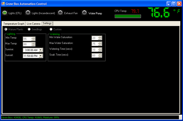
The Software — Grow box brains
Now I know all of this could be done with a Basic Stamp or Arduino pretty easy, but I wanted the ability to track history and have a decent user interface to look at, so I wrote a windows form application using C#. To cover the basic functionality of temperature control I used the parallel port outputs hooked up to the computer’s parallel port to give the software the ability to turn the lights on and off. By configuring a “sunset” and “sunrise” time which I am in complete control over the lights will turn on and off as appropriate. I added some logic to ensure the plants stay at a comfortable temperature (thresholds configurable) by turning on the incandescent bulb when it is too cold and an exhaust fan when it gets too hot. In order to allow the computer to know these temperatures I used a PS2 controller to create two temperature sensors one for the area the plants are growing and another for the top area where the CPU resides (computer was too old to have onboard temperature sensor)
My daughter thought it would be cool if we have some sort of automatic watering system. I agreed, so I added a moisture sensor and created an algorithm to periodically check the moisture level and activate a water pump to add water until it reaches the specified moisture level. I still need to buy and hookup the pump but coding portion is complete and tested.
I live in the Pacific Northwest it rains a lot and can get cold in the evenings and I don’t want to trek out to check on my plants. solved this by adding the computer to my Wi-Fi network now I can take look at them by connecting to the machine wirelessly and see how they are doing through it’s webcam. I also take periodic pictures of the plants so I can create cool time-lapse videos of progress like the one below. I also have the ability to browse through pictures taken at specific time periods.

Finally to store all of this data I installed SQL Server 2005 Express (free) which allows me to track historical data of the conditions and images over time. If you have data, you definitely need some graphs. Being too lazy to do this graphic work I leveraged ZedGraph (free) to allow some visual tracking of temperatures and moisture content.
Features for future versions (Beta 2?)
- Finish automated watering
- Add automated red LED lights for flowering stage
- Install LCD Panel
- Make box look better (real door which does not require tape to open/close)
- Create single USB controller for lights/sensors
- Better/additional camera
Video of grow box “booting” up, personally I like the flashing lights when the computer sends signal through the parrallel port. If you are old enough to ever have a printer that used a parallel port this is when it would make its annoying sound letting you know it was alive.
Updates:
Computerized Grow Box Update #1
Tags: arduino, cheap, garden seeds, grow lights, growbox, led, outdoor plants, strawberry plants, tomato plants, vegetables


